


Protect
The Protect module is your essential safeguard for preventing accidental incorrect applications of DC power from destroying your electronics.
It also doubles as a reverse-current blocking device that can be used for safely paralleling multiple power supplies or batteries.
We provide tested and proven solutions so that you can be assured your project has safeguards in place for unpredicted events.
📝 Overview
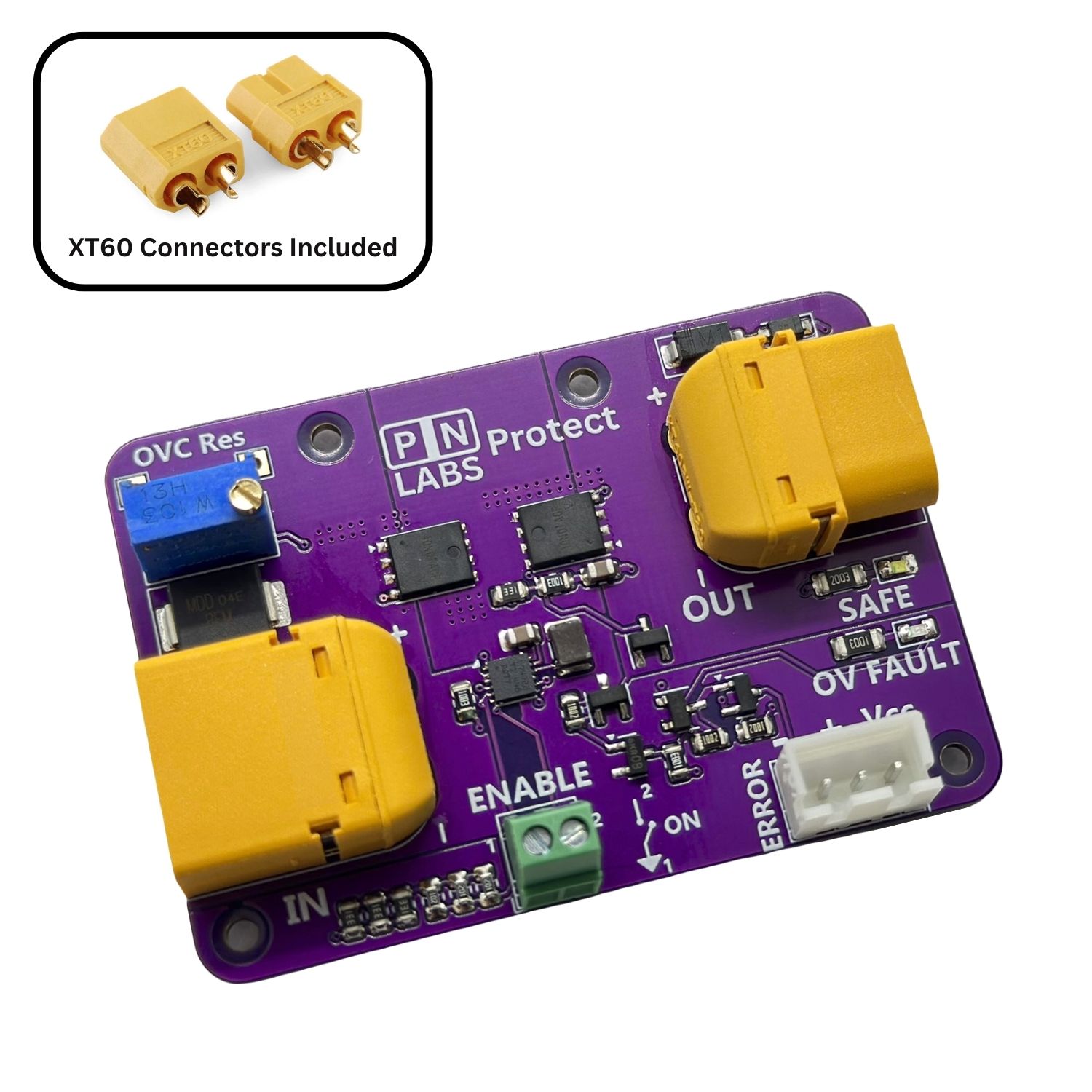
The PN Labs Protect is a compact, high-performance protection module designed to safeguard your DC-powered electronics from overvoltage, reverse polarity, and power supply mishaps.
It sits between your power source and load, continuously monitoring input conditions and disconnecting the load if unsafe voltages are detected—preventing costly damage.
Perfect for 5–30 V systems, Protect is ideal for robotics, makers, and industrial applications alike.
✅ Key Features
- Adjustable Overvoltage Protection (5–30 V):
Set your cutoff threshold by turning the onboard potentiometer. When input voltage exceeds the limit, Protect automatically shuts off output—and auto-recovers when conditions normalize. - Reverse Polarity & Reverse Current Protection:
Acts like an ideal diode with only a 13.5 mV typical voltage drop up to 14 A. Prevents damage from incorrect power connections and supports paralleling power supplies for redundancy (ORing). - Solid-State Reliability:
No relays, no clicks—just dependable, fast-acting MOSFET control. Designed for longevity and high reliability in demanding applications. - Power Switch Capability:
Use a low-current mechanical switch to toggle high-power loads via the Enable pin—no bulky high-current switches needed. - Microcontroller Fault Output:
Open-drain fault pin goes LOW during an overvoltage event—ideal for system diagnostics, alerts, or shutdown logic. - Dual Status LEDs:
- SAFE = Power is safely flowing
FAULT = Overvoltage fault detected and output disconnected
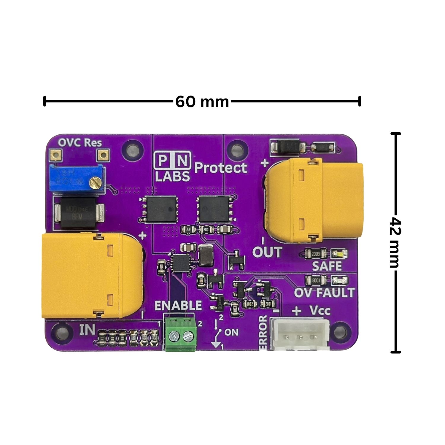
Compact & Mountable:
60 x 42 mm PCB with four M2 mounting holes. XT60 connectors make it easy to install inline with your system or stack multiple modules for ORing.
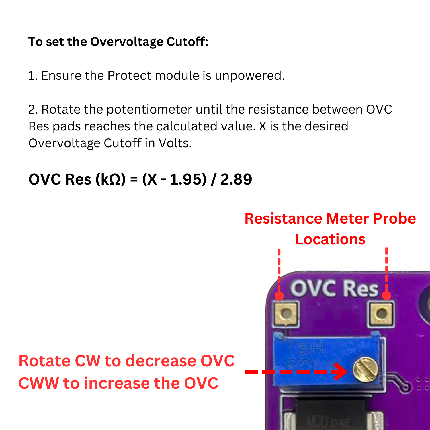
⚙️ Adjusting the Overvoltage Cutoff (OVC)
Overvoltage Resistance (OVC Res) Calculator
The Protect module allows users to precisely set the overvoltage cutoff threshold by adjusting the onboard potentiometer, which controls the resistance labeled OVC Res.
💡 Cutoff Equation
To calculate the desired cutoff voltage, use the following formula:
OVC Res = (OVC – 1.95) / 2.89
OVC Res is in kilo-ohms (kΩ)
OVC is your desired overvoltage shutdown voltage in volts (V)
You can measure the resistance between the test points with a multimeter while adjusting the potentiometer with a screwdriver. This provides fine-tuned control over the protection threshold.
Important: Always power off the Protect module before making adjustments to the OVC resistor to ensure current flow through the multimeter doesn’t affect its reading.
🚨 Overvoltage Protection Behavior
When the input voltage exceeds the configured OVC limit:
The Protect module disables the output within microseconds
The OV Fault LED turns on
The FAULT signal pin is pulled low (open-drain to GND)
The module will automatically re-enable the output once the input voltage falls approximately 0.5-1 V below the OVC limit, allowing seamless recovery after transient spikes.
⚡ Paralleling Protection Behavior
⚠️ Why would you need to use a Protect module instead of just directly connecting in Parallel?
When two unequal voltage sources are connected in parallel, the higher voltage side will attempt to charge the lower voltage side to bring them both to the same potential.
This uncontrolled flow of current can damage power supplies that are not designed to handle this, as the internal control loop will now try to compensate for what the other power supply is doing. In the case of a battery, an unregulated and potentially dangerous current spike will flow that may increase the maximum charging current of the battery, thereby damaging it by plating lithium on the anode and contributing to early failure.
The Protect module has an internal comparator which senses the voltage drop across the first MOSFET and shuts it off within microseconds if there is any reverse current flow detected, thereby saving your power supply.
In order for the power supplies to share the load, we have found that they generally need to be within 0.5 V or less of each other.
To operate the Protect module in Paralleling mode:
Use one Protect module per power source.
Set the OVC (overvoltage cutoff) limit on each module, or disable the limit by turning the OVC resistor to its maximum resistance.
Connect each power source to its own Protect module.
Join the output terminals of all Protect modules together to form the combined output.
(Optional) Add a switch to the Enable terminal on each module to individually turn power sources on or off, as described below.
🟢Normal Operation
When operating within safe voltage limits:
The Safe (green) LED is illuminated
The FAULT signal pin is pulled high to Vcc (via an internal pull-up)
🔌 Optional: High-Power Switch Function
The Protect module can also act as a main power switch for your system. Simply connect a single-pole single-throw (SPST) switch to the Enable terminal block:
Open switch = Module enabled (normal operation)
Closed switch (connect points 1 and 2) = Module enters low-power mode and disables output
This allows you to toggle high-current power delivery using a compact, low-current mechanical or digital switch.
📐 Product Specifications
Operating Voltage: 5 – 30 V DC
Maximum Continuous Power: 750 W
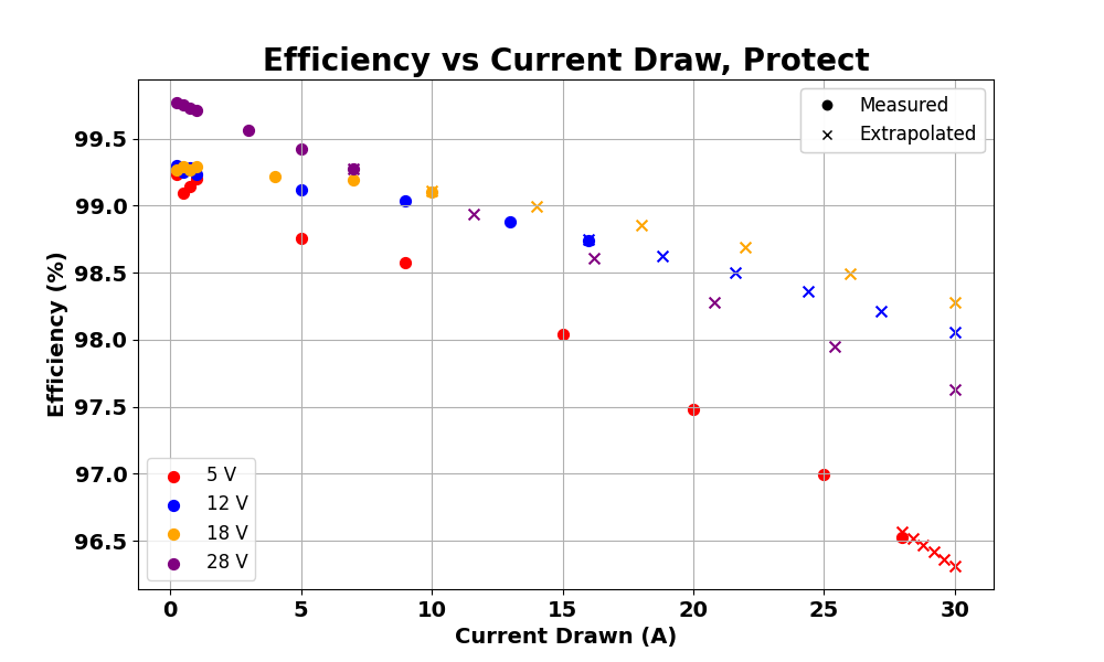
Maximum Continuous Current: 25 A @ 25 °C ambient
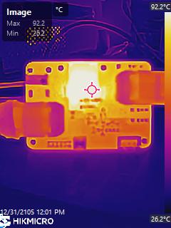
See thermal image and data below for performance beyond 25 A (up to 28.5 A stress tested).
Ambient Temperature Range: 0 °C to 45 °C
⚠️ Thermal Warning: Ensure the board temperature does not exceed 110 °C under any condition.
Overload Thermal Testing (5V 28.5A @ 25C Ambient - Least Efficient)
Dimensions
The board has overall dimensions of 59.75 x 41.5 mm.
Four M2 mounting holes are included and are dimensioned as shown:

What does this product do?
The PN Labs Protect module safeguards your electronics from overvoltage and reverse polarity by using a pair of back-to-back MOSFETs controlled by fast comparators.
When the input voltage exceeds a set threshold, the overvoltage comparator turns off the MOSFETs to disconnect the load. The shutdown point can be adjusted using the OVC resistor (see product description for the formula).
Additionally, the module monitors the rate of voltage rise (dv/dt). If it detects a voltage spike that’s predicted to exceed the safe threshold, it can proactively shut down the output—offering faster protection in rapidly changing conditions.
Why should I use this?
Placing this module between your power source and device can prevent damage from accidental overvoltage or reversed power connections. It reacts quickly to dangerous conditions, helping protect sensitive electronics from failure. The exact reaction time depends on your system’s load and sensitivity.
What if it doesn’t work?
We take quality seriously. Every Protect module is tested in-house before it ships, using automated testing equipment to verify it works as expected.
If you receive a module that isn’t functioning properly, contact our support team and we’ll make it right. Support
Reviews
Nice Documentation
Module arrived quickly and it had the connectors nicely packaged in the same ESD bag as the module. It also had the PN Labs website listed on it which turned out to have a ton of additional technical information about the module. Thermal information was nice to see and it also had a step file which I do not need currently, but would be useful in a larger future project.
I did not see how to set the overvoltage limit on the Amazon page, but the website had a handy calculator for it if anyone else runs into that issue.
Makes my project feel more safe, adds an extra level of security
I am not into designing printed circuit boards and electronics so having this module makes me feel better that my robot is protected against accidentally applying too much voltage. I’ve broken other stuff this way before so it really helps to have something for peace of mind. It’s nice that this company gives you the CAD file of the board on their website which I use with my SolidWorks assembly.
This one works as advertised. Other options don’t…
I’ve had issues with other overvoltage protection modules in the past. Many of them claim to handle up to 36V, but the relays are clearly marked with a maximum voltage which is usually 14V or 25V. After only a couple of weeks of use, the other one I tried died. It claimed a max input voltage of 36V but the relay label stated a maximum voltage of 14V DC. I was using 24V.
After trying a couple other modules for my project, I went with this one because is its simpler to set up with the included connectors, keeps its programmable threshold even if you lose power, and uses transistors instead of relays which are faster and more reliable.
Decent module, connectors are included
Product works great. I bought this because I destroyed my previous robot (expensive servos + raspberry pi, driver shield) by accidentally putting 15 V instead of 6-8 V from my adjustable power supply 🙁 I bought one of these and was impressed at its response time.. I set the limit to be 8 V and tried applying 15 V to the shield and it shut off instantly with no damage.
The XT60 connectors are a bit heavy duty for what I’m doing but it’s nice that they’re included!